Chokes

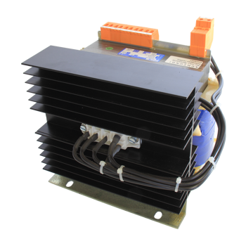
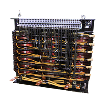
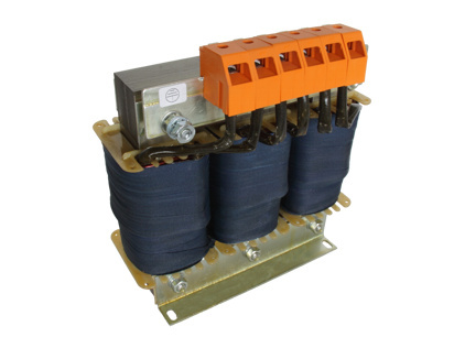
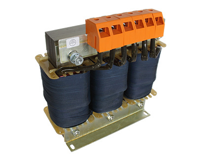
Chokes are used to provide an inductive resistance and since they can be matched to practically all requirements they have a correspondingly wide field of application. Chokes can be overloaded to a high degree for short periods provided they can cool adequately afterwards. When used as current limiters the value for overload and short-circuit protection must be carefully selected because chokes can, for example, restrict short-circuit currents to such an extent that short-circuit instantaneous releases do not operate. A thermocontact integrated in the choke with subsequent disconnection would in this case provide protection against overloading.

However, ambient temperatures above 40°C and installation altitudes of more than 1000 m above sea level mean that less power can be drawn.

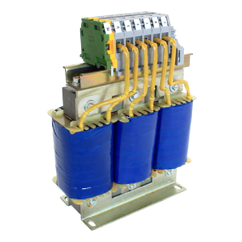
Chokes generate distinctive stray fields. Care should therefore be taken when installing them to ensure firstly that these stray fields are not bridged and secondly that there is no heating of adjacent components. Chokes are generally designated according to the application. For example:

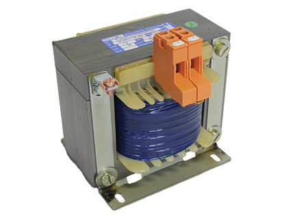
Smoothing chokes reduce the current ripple in the output of rectifier circuits and act as a magnetic energy store whose size is determined by the energy content.

Energy content W = 0,5 x L x I²

L= Inductance of the smoothing choke in H
I = Arithmetic mean value of the direct current in A

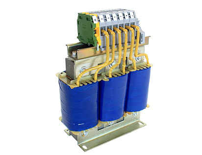
Commutation chokes limit short-circuit currents which occur in rectifiers during current transfer between semiconductors. The size of commutation chokes is dictated by

  Rated voltage in V
Impedance voltage in % of the rated voltage
Rated current in A

Starting chokes limit the starting current of electric motors and are designed for short-time operation. Taps are provided for multi-stage starting. The size of starting chokes is defined in kW according to the motor power.

Naturally we also make chokes for other applications, for example

  Filter chokes
Resonant frequency chokes, etc.

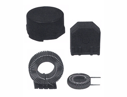
and other types of construction, e. g.

  Air-core chokes
Toroidal chokes, etc.
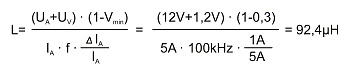
The series of chokes described on the following pages with their dimensions and parameters only provide an approximate overview since chokes can be matched to customers' requirements by changing some of the variables.

Power ratings and models which are not listed are available on request.


Smoothing Chokes GD 180 - 5000mWs

Smoothing Chokes to VDE 0570/IEC61558
  • Energy content 180 – 5000 mWs
  • Frequency 100 Hz / 300 Hz
  • Base bracket mounting
  • Terminal blocks shockproof to VBG 4
  • Insulation class ta = 40°C/B
  • Class of protection I
  • Type of protection IP00

Download Fact Sheet


Three-Phase Commutation Chokes DKD 10 - 200A

Three-Phase Commutation Chokes to VDE 0570/IEC61558
  • Current range 10 – 200 A
  • Frequency 50 Hz/sine
  • Rated voltage 400 V
  • Impedance voltage 4 % (9.2 V/phase)
  • Base bracket mounting
  • Terminal blocks shockproof to VBG 4
  • Insulation class ta = 40° C/B
  • Class of protection I
  • Type of protection IP00

Download Fact Sheet


Three-Phase Starting Chokes AD 1,5 - 30kW

Three-Phase Starting Chokes to VDE 0570/IEC61558
  • Motor power range 1.5 – 30 kW
  • Frequency 50/60 Hz/sine
  • Rated voltage 400 V
  • Starting current limited to 3 x rated current
  • Base bracket mounting
  • Terminal blocks shockproof to VBG 4
  • Insulation class ta = 40° C/B
  • Class of protection I
  • Type of protection IP00

Download Fact Sheet


Three-phase filter chokes FKD

Three-phase filter chokes to VDE 0570 / EN61558 and IEC 76
  • frequency 50 Hz
  • rated voltage 400V
  • type of cooling AN
  • base bracket mounting
  • terminal blocks or cable lug
  • insulation class ta = 40° C/B
  • class of protection I
  • type of protection IP00

Download Fact Sheet 1
Download Fact Sheet 2


Storage Chokes

Storage chokes are typically used in switched-mode power supplies. Their function is to store the energy which is absorbed by the choke during the conduction phase. In the blocking phase they then supply the stored energy to the series-connected load or the smoothing capacitors. The constant rise and fall in the choke current results in an approximately triangular current waveform at the storage choke.

The storage energy W is derived from the inductance L and the choke current I according to the following formula:

W = ½ x L x I²

As a result of the increasing miniaturization of switched-mode power supplies and the requirement to set the clock frequency of the valves used in the switched-mode power supplies above the range of audibility, it is normal to work with switching frequencies in the range from 20 kHz to 100 kHz. These high frequencies which are applied to the chokes make it essential to use high-quality cores. The high frequencies result in high power losses which vary according to the core material and the core volume. These heat up the storage choke and put severe constraints on the conditions for use as far as the ambient temperature is concerned. GETRA therefore use cores made of high-quality materials such as MPP (molyper-malloy) and HF (High-Flux) which are suitable for high frequencies and are characterized by low core losses. As an alternative, however, low-cost cores of ferrous powder are also used.

The main parameters which are important for selecting the size of a storage choke are:
  • direct current preloading
  • current ripple
  • pulse frequency
  • ambient temperature
The direct current preloading results in a drop in the inductance at rated current compared with the no-load inductance. The permissible current ripple requires maximum saturation of the core material and is thus in direct relation to the core losses. The pulse frequency controls the inherent heating of the storage choke through the core losses and thus determines the maximum permissible ambient temperature.

Finally an example of how to select the right size of storage choke is shown below.

Given the following basic data for a switched-mode power supply:

UA=12V; UV=1,2V; IA=5A; ∆I=1A; f=100kHz; Vmin=0,3

mit:

UA Output voltage
UV Voltage loss at the diode and the storage choke
IA Output current
∆IA Residual ripple of the choke output current
f Pulse frequency of the switched-mode power supply
Vmin Minimum pulse duty factor

The required inductance L can be determined with the following formula:


GETRA´s success is no secret.

Our principle was and is to act in a forward-looking manner. In doing so, we attach a great deal of importance to quality and an optimal price performance ratio. We have high standards when it comes to our products, which are of course built and tested in line with the requirements of the VDE and DIN guidelines, and for this purpose, we have certified our quality management system according to ISO 9001!


but-top